Potentiometer

Potentiometer is an electronic component. It works as a variable resistor. A Potentiometer consists of a high-resistance wire of manganin or germanium silver and a variable knob that provides variable voltage to various electronic circuits. It is also named as a voltage divider. It has three terminals. The external two terminals are connected to the supply voltage while the central terminal or middle terminal provides variable voltage to various circuits. Potentiometer provides variable voltages while the Rheostat or Thermostat provides variable resistance. The main function of the potentiometer is to provide variable voltage to different electrical and electronic devices and circuits. A potentiometer is also used for the measurement of voltage across a resistive element of a circuit. It is also used to compare the EMFs of various electrical parameters. Potentiometers have many types according to electric current and its function like Linear Potentiometers, Rotary potentiometers, AC Potentiometer, DC Potentiometer, Logarithmic Potentiometer, Trimmer Potentiometer, Digital potentiometers, etc.
So, let’s discuss the types of potentiometers which are used in many circuit boards and in electrical as well as electronic devices for various purposes according to their various functions and operations.
Symbol
Potentiometer is a three-terminal electronic component and it consists of a resistive element and a wiper that gives variable voltage to various electric as well as electronic circuits. The symbol of the potentiometer is shown below:

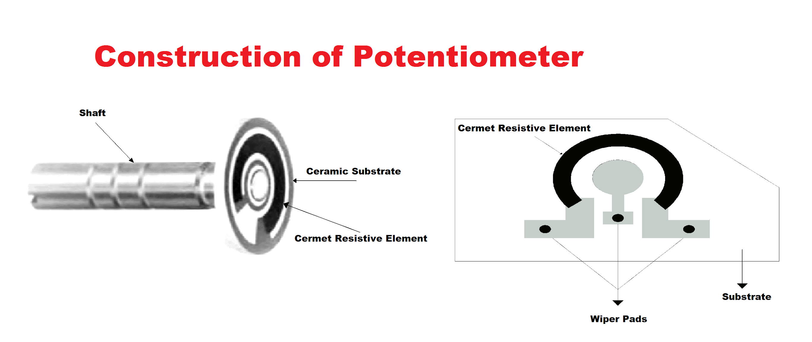
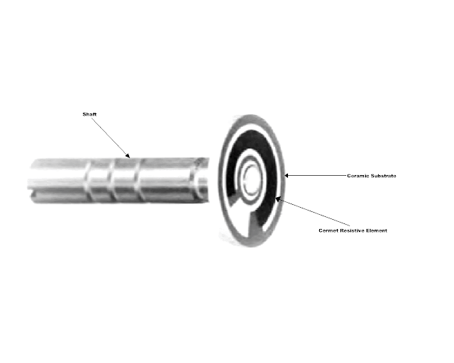
Construction of Potentiometer
Potentiometer consists of the resistive element, terminals, contact/wiper, actuator/shaft, and casing. The resistive element is the main part of any potentiometer. The resistive elements are of two types: wire-wound and non-wire wound. The non-wire wound element is of cermet, carbon, metal film, or bulk metal.
Resistive Elements
Resistive elements are of various types and these types are explained below:
Wire-wound Elements
Wire-wound elements are made up of nickel-chromium, copper-nickel, gold platinum, and nickel-chromium. Nickel chromium consists of 800 ohms resistivity per circle mil foot (cm). A circle mil foot is equivalent to one foot of wire. It is most commonly used in potentiometers because of its excellent efficiency and availability in various diameters. Copper-nickel wire has a resistivity of 300 ohms/cm. The resistive elements depend upon the total required resistance. The smaller wire allows higher resistance and smaller wires are difficult to wind. This wire-wound element is cut into individual rings for single-turn potentiometers and multi-turn potentiometers. Wire-wound potentiometers provide very good stability of total resistance and these elements have low noise in static state and have high power capabilities.
Non-wire Wound Elements
The variable resistive devices which have no resistance wire in them are non-wire wound devices. These elements are also used in potentiometers. These elements are divided into many sections according to the resistive materials which are described below:
Cermet Resistive Elements
Cermet is a term used for materials that are made up of different elements from different sources. Cermet materials are made up of ceramic or glass with a combination of different precious materials to form a ceramic metal resistive material. Cermet is also known as a thick film which is a resistive and conductive film greater than 0.0001 inches thick in the form of a paste. These are deposited on a ceramic substrate. The paste is applied to the flat ceramic substrate by silk screening operation. Cermet elements offer very low resolution and have good stability. These materials do not produce noise while performing the operation. This technique is also used for the manufacturing of hybrid circuits and fixed resistors.
Carbon Elements
Carbon elements are made up of carbon powder and phenolic resin. It is in the form of liquid. This liquid is sprayed on the substrate. When the resistive material is applied on the substrate then the resistive element is transferred to an oven for curing. This process is done by infrared curing. Carbon elements have low cost and low noise during adjustments. Carbon elements have poor moisture resistance and poor load stability as compared to cermet elements.
Metal Film Elements
A very thin layer of metal alloy is applied on a substrate and the case/casing or cover is filled with vacuum. Any metal which can be evaporated is used as a resistive element. Normally a nickel-chromium alloy is used because the other materials cannot fulfill the requirements. Metal film elements cannot produce high reactive impedance. Metal film elements are only used for low resistance values. These elements are used from 10 ohms to 20K ohms.
Bulk Metal Elements
These elements are made up of bulk or mass metal. This metal is applied to the substrate. Its layer is thicker than the other elements on the substrate. The plating technique is used to apply this resistive element on the substrate. These elements are used in trimmer applications. These are expensive elements.
Hybrid Elements
A hybrid element consists of a wire-wound element with a conductive plastic coating. Hybrid elements exhibit the temperature coefficient and resistance stability of the wire-wound element and the long operational life. These are costly because of the extra processing on them.

Terminals
Terminals of the potentiometer are of different types which are shown below:

The terminations of the potentiometers are different from each other because of the various resistive elements in it. The terminations of the major element types are discussed below:
Terminations of wire-wound Potentiometers
Wire-wound potentiometers have four different methods for the terminations of resistive elements. These methods are:
- Single wire type
- Silver braze type
- Pressure clips
- Solder

Contact / Wiper
Contact is a part of the shaft of the potentiometer and this part is named as contact or wiper. This wiper is used to make a connection between the potentiometer’s terminals and the resistive element. It plays an important role in every potentiometer. This contact must be connected with resistive elements and external terminals in ceramic potentiometers. These contacts are made up of a metal alloy that has its own spring force.
Actuator / Shaft
A component or a part of a potentiometer that moves the wiper/contact across the resistive element is known as the actuator/shaft of a potentiometer. These shafts come in many types according to their shape and size. So let’s discuss some types of actuators/shafts.
Rotary Shaft Type
These actuators are cylindrical shaped with a knob on its head. These actuators rotate in a circular position which is why these actuators are named as rotary shaft type. The wiper is connected to its end which is used to make contact with the external terminals and a resistive element. This wiper is insulated with the shaft. The wiper is connected to the additional sliding contact. This sliding contact is connected to the resistive element and the wiper easily makes contact with the resistive element and the external terminals.

Lead Screw Actuators
Lead screw actuators are used to fix the adjustments of the resistive elements according to their requirements. These are cylindrically shaped. These actuators are made up of steel and the wiper is attached to its end. This wiper makes contact with the external terminals and the resistive element directly. These actuators have a knob on their head for the adjustments of the resistive element. These actuators were used on old-age potentiometers.

Worm Gear Actuators
The Potentiometer which consists of Greater length of resistive element consists of worm gear Actuator. If the element is formed in a circular manner, then the adjustment screw worm engages the teeth of a small plastic gear. The Wiper is placed between the plastic gear. When the gate is rotated by the worm gear actuator adjustment screw, the viper moves long to the element. If the direction of the adjustment screw rotation is reversed, the Viper correspondingly begin to move immediately.

The Single Turn Direct Drive Actuators
It consists of a simple router with the slot and mechanical stops which are used in rotary adjustments of the wiper position in a single turn unit. In this actuator, ring seal is used to prevent from moisture and it also provides friction which serves as a mechanical restraint. this actuator is a lower cost unit and it cannot provide sealing feature.
Linear Actuator
It is used for servo applications. The viper is directly connected to it and it make contacts between the external terminals so that a linear motion causes a direct linear travel of the wiper these actuators are used as Precision linear position feedback transducer. These are several feet long. These types of potentiometers are frequently used on audio level control panel which is used in audio recording studios. It has the capacity to make Rapid changes and visually compare relative settings in an instant.


Housing / Casing / Case
Housing of a Potentiometer is very important in potentiometers because it holds various components of Potentiometer in it. The casing of Potentiometer has a stability and quiet performance by shielding the resistive element and contact/ wiper surfaces from dust and dirt. It is a mechanical structure which holds the external terminals and it provides protection to external terminals from mechanical destructions. The casing prevents mechanical and electrical installation from various affects.
Types of Potentiometer
The major types of potentiometers are Linear Potentiometers and Rotary Potentiometers. All the types of potentiometers according to their function and operation are mentioned below:
Linear Potentiometer
Linear potentiometers use wire-wound resistive element in it. These are not rotated in a circular position. These potentiometers consist of a slider which moves from top to bottom or from bottom to top in a linear position. The wire-wound resistive element is connected to the wiper and this wiper is connected to the slider and this slider gives variable voltage on its central terminal when it moves from one end to other end in a straight line.
The battery supplies the current through the rheostat and a slide wire. The current of slide wire changes when the rheostat is adjusted.
Types of Linear Potentiometer
Membrane Potentiometer
Membrane potentiometers are the type of Linear potentiometers and these potentiometers move in a linear direction with the help of a slider. Membrane potentiometers uses membrane material in it. Three types of membrane materials are used in these potentiometers which are as follows:
- Membrane as a wiper
- Membrane as a resistive element.
- Adhesive film
All these membranes are separated with spacers. These membrane layers are connected to each other with the mechanical wiper. The contacts of membrane potentiometers are achieved by the mechanical wiper / contact.
Multi Turn Potentiometer
Multi turn potentiometers have multiple turns of resistive element and that is why these are named as multi turn potentiometers. These potentiometers are a type linear potentiometer. In multi turn resistive element, the wire is wrapped with each other and the element consists of multiple turns of wire of resistive element. These multi turn potentiometers are used for large electric supplies. The potentiometers consist of a slider which moves in a straight line and provide variable voltage.
Single Turn Potentiometer
These potentiometers consist of a slider which moves on a resistive element. The resistive element consists of some turn of nichrome wire and these turns are separated to each other. These potentiometers are used on low power circuits and provides minimum voltage.
Rotary Potentiometer
Rotary potentiometers have rotatable shaft and this shaft is connected to the cermet resistive element with a wiper/contact. When the shaft/actuator rotates, it provides resistance on its circuit on which it is connected. It also gives the divided voltage. Rotary potentiometers usually have carbon material resistive element because it provides stability and efficient in dividing voltages.
Types of Rotary Potentiometer
Logarithmic potentiometer

Logarithmic potentiometer is a type of rotary potentiometers and these potentiometers work according to the logarithmic scale. These potentiometers consist of cermet resistive element and a wiper which makes contact between the resistive element and rotatory knob of potentiometer. The whole construction of logarithmic potentiometer is same as rotary potentiometer. Logarithmic potentiometers provide logarithmic functions on its output voltages. These give logarithmic values / fixed values on different position of resistive element. Some potentiometers cannot provide accurate logarithmic voltages.
Logarithmic potentiometers are used in volume control panels, audio voice control circuits and tone controls etc.
Arduino Potentiometer
In Arduino Circuit board, rotary potentiometer is used in it. As the Rotary potentiometer is used in Arduino circuit board so these are named as Arduino potentiometers. Rotary potentiometers are used to control the speed of DC motor. The circuit diagram of DC motor speed control is shown below:

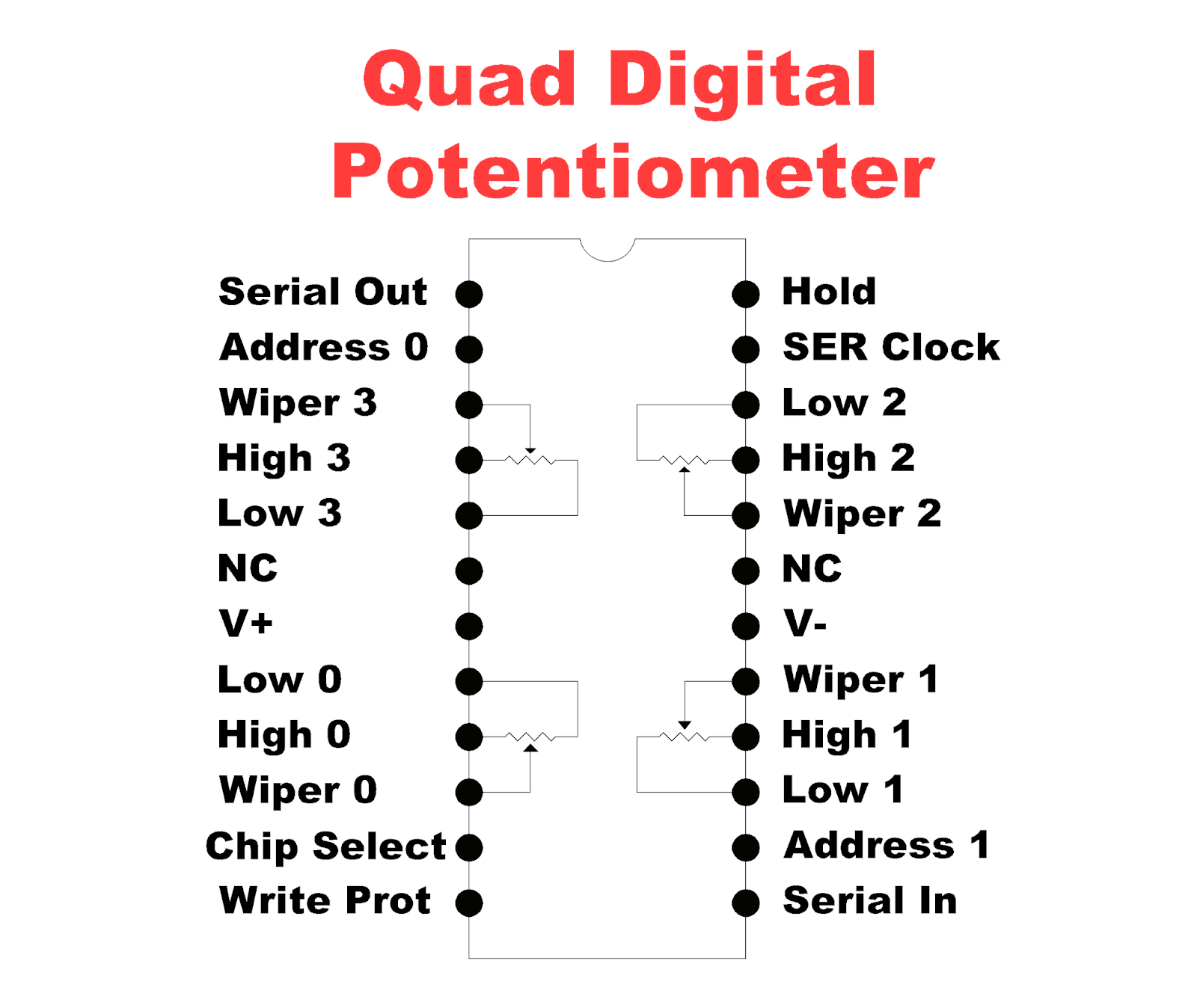
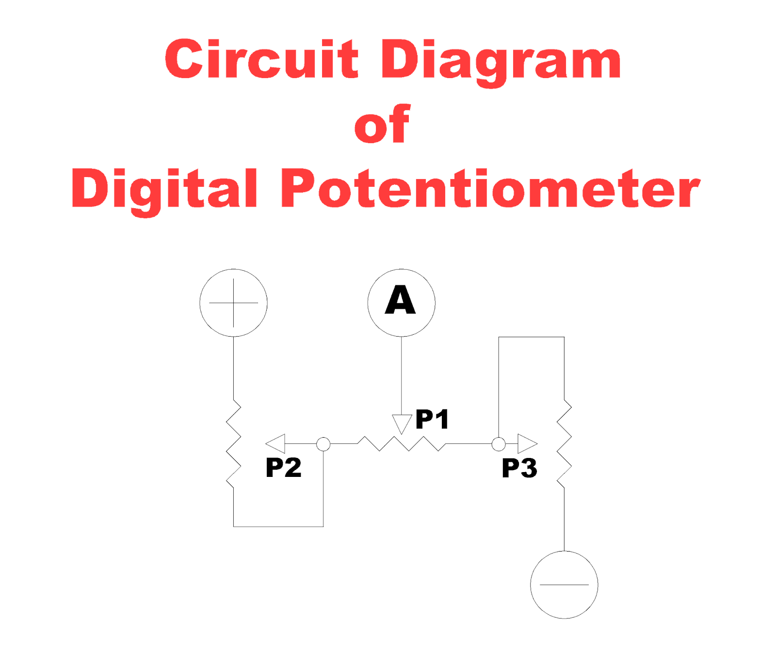
Digital Potentiometer
It is a mixed signal device which enable digital control of a variable voltage. Digital potentiometers are also known as digitally adjustable potentiometer, digi-pot or digital programmed potentiometer. This is an integrated circuit chip which works by means of programming. These potentiometers are used for the adjustment of the pulse width of an oscillator. Digital potentiometer consists of a ladder resistances and it allows access to each end of the ladder through two pins as a high and low. The high pin is numbered 1 and the low pin is numbered 1. These potentiometers are designed for 5v supply or less.

Most microcontrollers contain one or more analog digital converters that convert analog input into numeric value. Microcontrollers cannot create analog output but the problem is that these converters are operated on low currents.
An Up/Down digital potentiometer is controlled by the pair of push buttons. One push button increases its resistance value and the other push button decreases its resistance.
The resistance of microcontroller / digital potentiometer increases and decreases step by step. Once pressing the push button, the resistance increases slightly and same as decreasing. These push buttons are not so successful and a rotational encoder is used which emits stream of pulses when its shaft is turned. In this case, another component is used to interpret the pulse stream and change it to a format that the digital potentiometer can understand.
Advantages of Digital Potentiometer
These potentiometers are reliable because these are used as many times and these are capable of adjustments of voltage.
These potentiometers have digital interface and works properly and so fast.
Digital potentiometers reduce capacitive affects from signals.
These potentiometers are weightless in size.
Disadvantages of Digital Potentiometer
Its internal resistance is affected by the temperature.
It cannot pass significant current from it.
Users prefer a rotational knob rather than the push buttons or rotational encoder.
Trimmer Potentiometer
Trimmer potentiometers are one of the applications of potentiometer. This potentiometer is used in electronic circuit boards and these are also used in electronic chips of various electronic devices. These trimmer potentiometers are used to provide variable voltages to various electronic components and according to their requirements. These are very useful in electronic circuits. Trimmer potentiometers consist of a knob which is adjusted to the requirement of various input values. These also uses cermet material resistive element.
Types of Potentiometers with respect to Measurement
DC Potentiometer
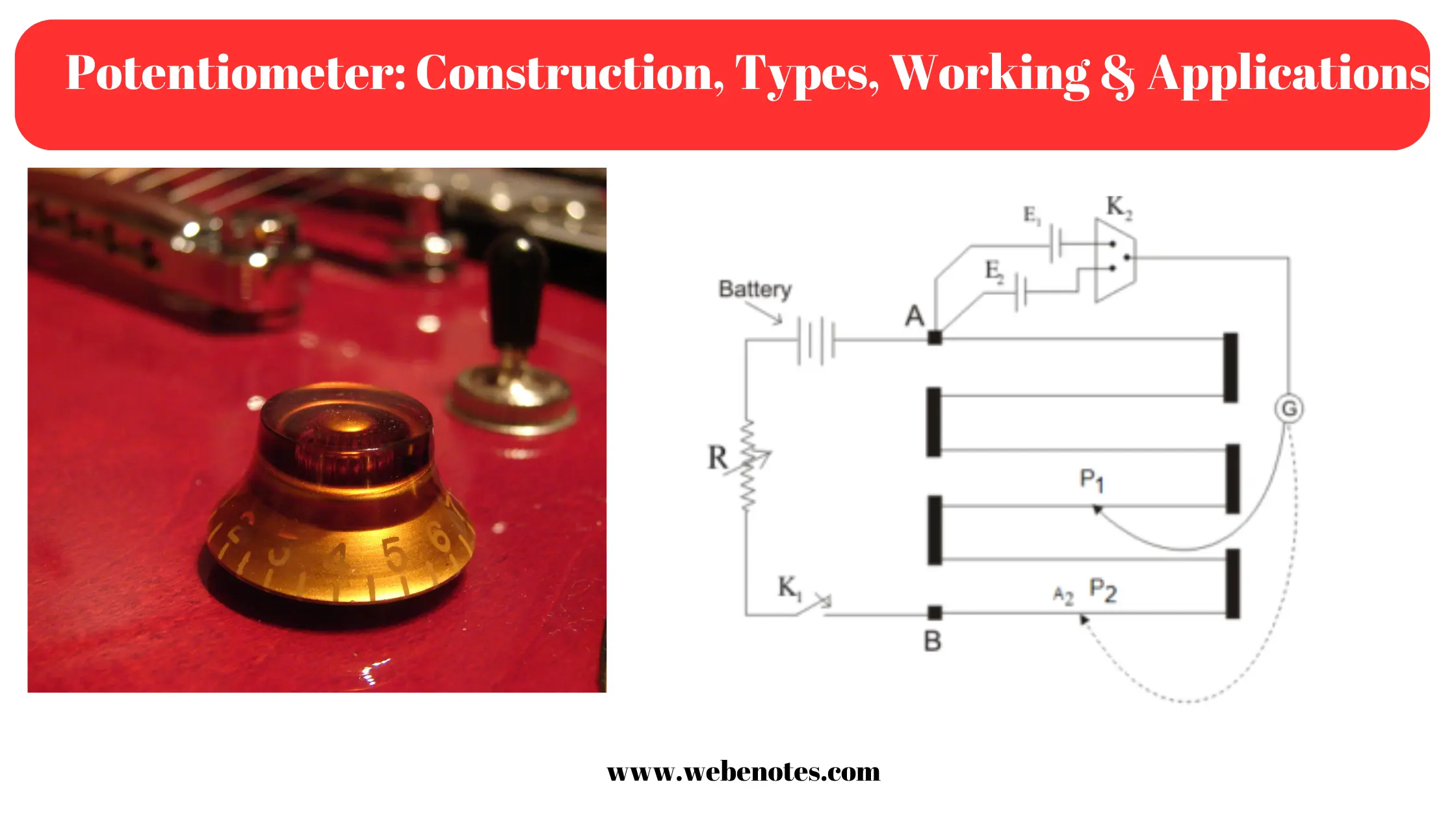
A DC Potentiometer is used for the measurement of EMF’s of different cells and for calibrating the voltmeters, ammeters, wattmeters etc. These potentiometers consist of a germen silver or manganin wire. This wire is one meter long and it is stretched between two terminals. This wire is connected with Rheostat in series. As shown in figure below:

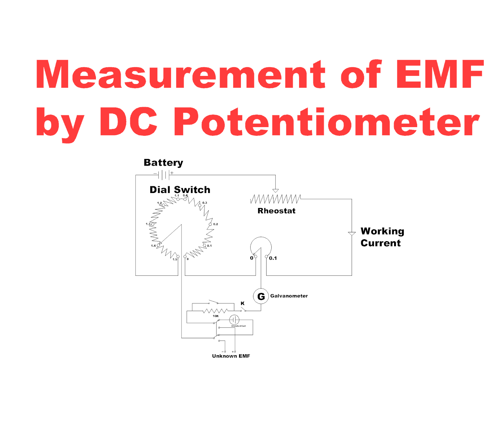
Measurement of EMF by DC Potentiometer
The switch and the slide wire are set to the standard cell voltage. The standard voltage are 1.01 volt. The switch S is in calibrate position and the galvanometer switch K is pressed when the rheostat is adjusted to zero. A 10Kw resistance is included in a circuit to protect the Galvanometer from overloading. When the null deflection on the galvanometer is come near, then the protective resistance is shorted to increase the sensitivity of the galvanometer. The rheostat is adjusted for the deflection of galvanometer. Now, the switch is closed to connect the unknown emf with the protective resistance in the circuit. The potentiometer is adjusted by means of a main dial and a slide wire. The balance is obtained and the value of unknown EMF is measured.
Applications of DC Potentiometer
DC Potentiometer is used for the measurement of various electric parameters and for the calibration of different instruments. The uses of DC potentiometer are described below:
- Measurement of Electric Current
- Measurement of Voltage
- Measurement of Resistance
- Measurement of Electric Power
- Calibration of Ammeter
- Calibration of Voltmeter
- Calibration of Wattmeter
So, let’s discuss all these measurements and calibrations of instruments with the help of DC Potentiometer one by one:
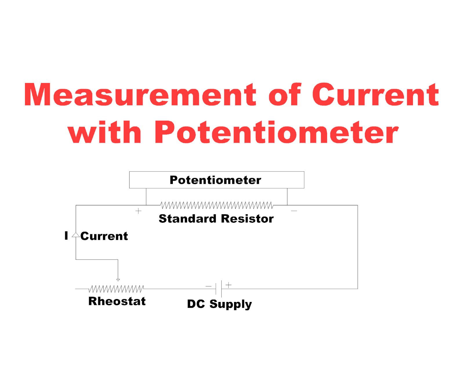
Measurement of Electric Current
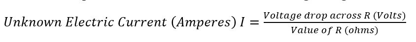
In this method, the current which is to be measured by the DC potentiometer is passed through the standard resistance / resistor R as shown in figure. The standard resistor should be of a value by which voltage drop are caused with the flow of electric current which is to be measured and its value may not be exceeded to the value of the potentiometer. The following formula is used to measure the unknown electric current in amperes from this circuit which is shown in figure is given below:
Measurement of Voltage
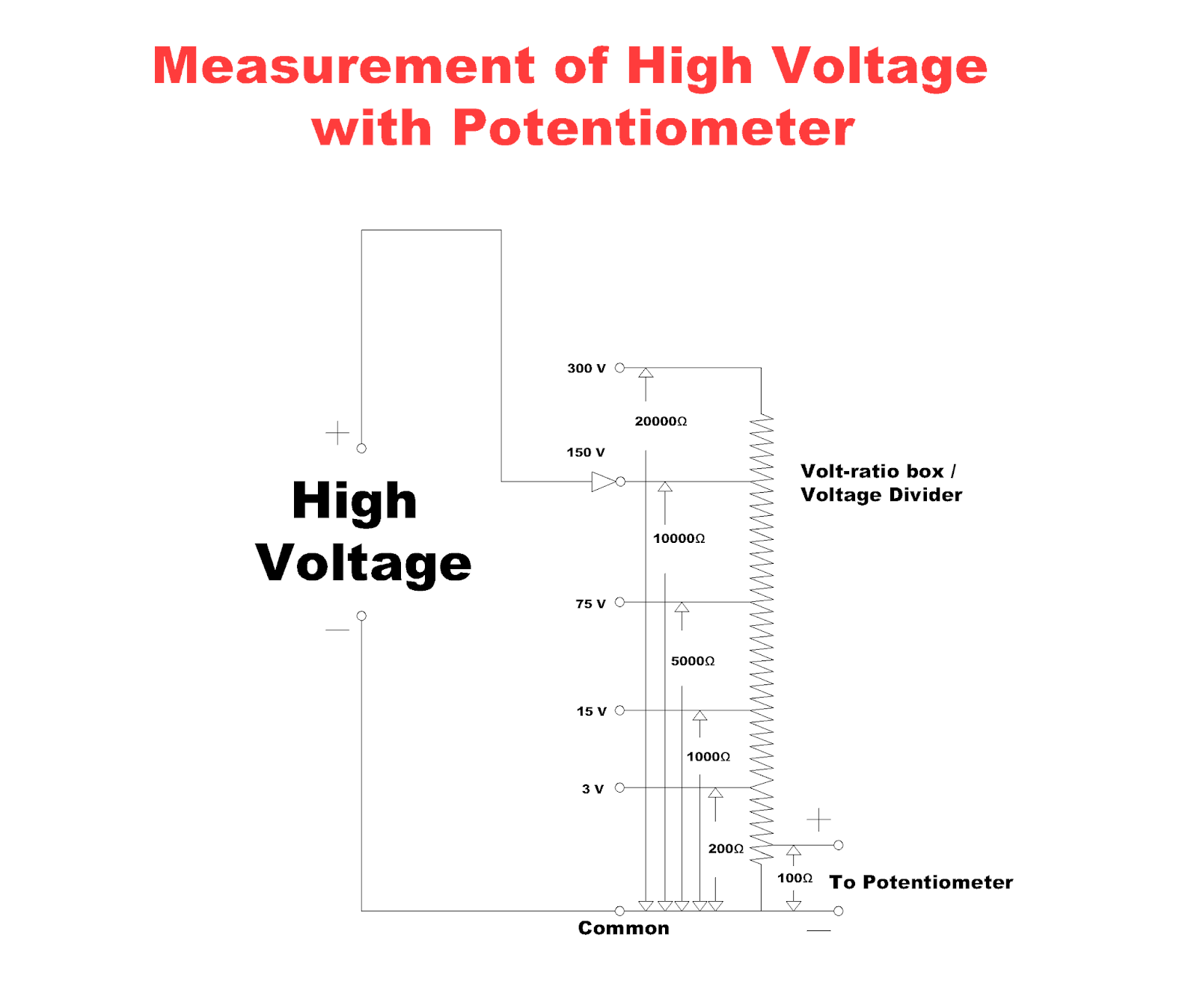
In this method of measurement, DC potentiometer measures the high voltage. These high voltage are measured by the volt-ratio box with the potentiometer. This box consists of simple resistance with the various tapping on its input side as shown in the figure. Each input terminal has its own maximum voltage and these are corresponding to the multiplying factor for the voltage scale.
High voltage are applied to the input terminal of the volt-ratio box/voltage divider and these high voltage leads to the potentiometer through the voltage divider and the two points are taken by the potentiometer from the volt-ratio box. The high voltage are measured by the potentiometer. The formula to measure the high voltage is given below:
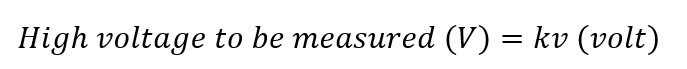
Where, v are the voltage measured by the potentiometer and k is the multiplying factor of the volt-ratio box.
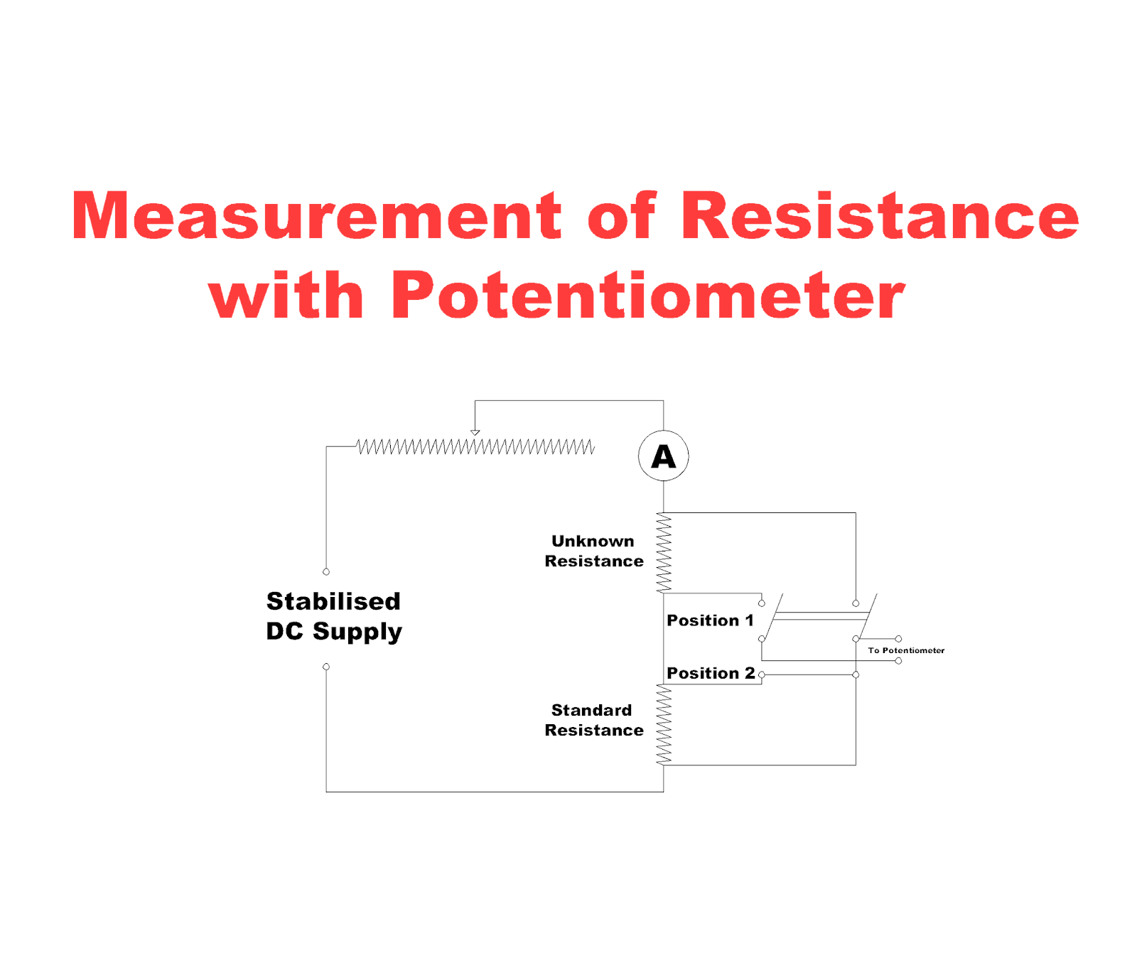
Measurement of Resistance
The resistance which is to be measured is connected in series with the standard resistor. The rheostat is connected in this circuit to control the electric current and an Ammeter is also connected in series with the rheostat and it is used to indicate the value of current is within the limit of the potentiometer or not. The two pole double throw switch is connected between the unknown resistance which is to be measured and the standard resistance. When this switch is put into 1 position, the unknown resistance is connected to the potentiometer. The reading of the potentiometer is in VR. then,
And when the switch is thrown to the 2 position, the standard resistance S is connected to the potentiometer. This reading of the potentiometer is in VS then the value of unknown resistance is measured correctly. The formula is given below for the measurement of resistance:
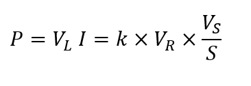
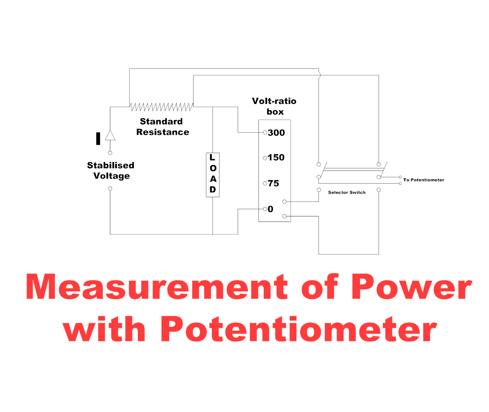
Measurement of Electric Power
In this method, the standard resistance is connected across the load. The voltage drop are divided across the standard resistor then the load current will be,
Where VS are voltage drop across standard resistor as measured by the potentiometer. The total power consumed in a circuit is given below in the form of formula:
Calibration of Voltmeter
In this calibration, a stable DC voltage supply is used and a potential divider network is used which consists of two rheostats. One rheostat is used for coarse and the other is used to control the calibrating voltage. These controls are used to adjust the supply voltage. The volt-ratio box steps down the voltage across the voltmeter. These voltage are suitable for the voltmeter reading. The potentiometer measures the accurate value of voltage and if the reading of the voltmeter and potentiometer does not match with each other then there will be opposite connections of the voltage supply in the circuit.

Calibration of Ammeter
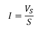
In this method, standard resistor is connected in series with the ammeter. This resistor
carries high value of current. The voltage drop and the current is measured across the standard resistor with the help of potentiometer by dividing the voltage across the standard resistor with the standard resistor value. The following formula is used to measure the current from potentiometer:

Where VS is the voltage across the standard resistance and S is the value of standard resistance.

Calibration of Wattmeter
In this method of calibration, the current coil of the wattmeter is connected to the low voltage supply and the voltage coil is connected to the normal supply through the voltage divider. The voltage across the voltage coil is measured by the potentiometer directly. The current of the current coil of wattmeter is measured by measuring the voltage drop across the standard resistance.
The power will be VI where V is the voltage across the voltage coil and I is the electric current through the current coil of the wattmeter.

AC Potentiometer
The working principle of AC Potentiometer is same as the working principle of DC Potentiometer. The main difference in AC and DC Potentiometer is that the DC Potentiometer measures the magnitude of EMF by standard cell but the AC Potentiometer measures the magnitude and the phase angle of the unknown voltage to compare the achieved balance.
Classification of AC Potentiometer
AC Potentiometers are classified into its two types which are as follows:
Polar Potentiometer
In Polar Potentiometer, the EMF is measured in polar form. In other words, the EMF is measured in terms of its magnitude and its phase angle Θ. The magnitude and the phase angle of the EMF is indicated by separated scales. Polar potentiometers are classified into its one type:
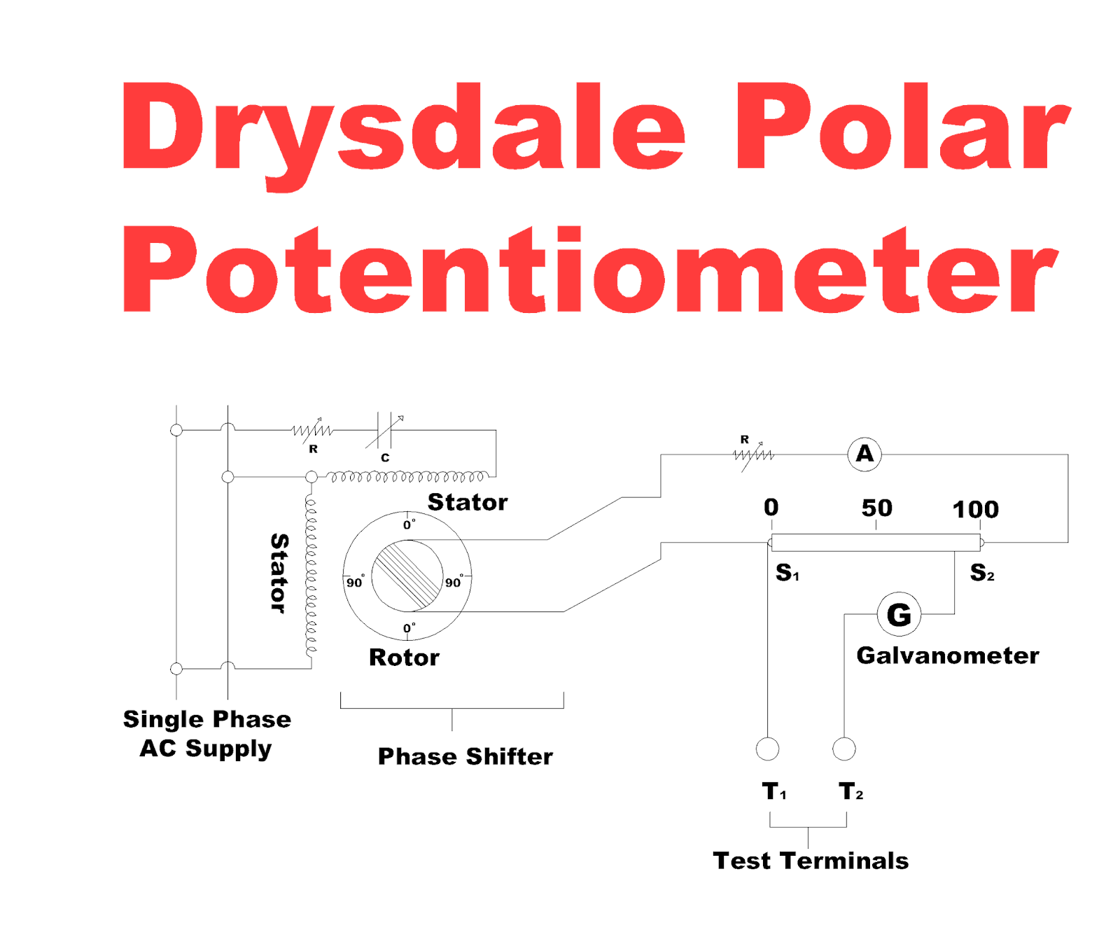
Drysdale Potentiometer
In this potentiometer, a slide wire S is used and the terminals of slide wire S1 and S2 is supplied from a phase shifting circuit for AC measurement. The voltage supplied by the phase shifting circuit remains constant and the slide wire current is constant but it varied in phase. The phase shifting circuit consists of two stator coils which are connected in parallel to the same supply. A mechanism is used to differ these currents by 90o in phase shifting circuit. The two windings produce rotating flux and induces a secondary emf in the rotor winding of a constant magnitude. The phase of the rotor EMF is observed from circular dial which is attached in the potentiometer. The potentiometer is calibrated by the DC Supply for slide wire and standard cell for test terminals T1 and T2. The unknown AC Voltage are measured across the test terminals. The ammeter is connected to the slide wire circuit and it gives the magnitude of the unknown emf and the circular dial in the rotor circuit gives the phase angle of it.
Coordinate Potentiometer
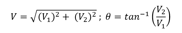
This potentiometer measures the unknown EMF in certasian form. The two components along and perpendicular to some standard axis which are measured by two different scales which are known as in phase V1 and quadrature V2 scales. The formula to find the unknown voltage by this potentiometer is given below:
These potentiometers are classified into its one type:
Gall Coordinate Potentiometer
Gall coordinate potentiometer consists of two separate potentiometer circuit. One is the In Phase Potentiometer and the other is the Quadrature Potentiometer. The two currents are supplied to these two potentiometers. The slide wires of these two potentiometers are balanced to obtain the value of unknown voltage. The magnitude of the unknown voltage is measured by the following formula:
And the phase angle of the unknown EMF is:
R and R’ are the two Rheostats used to control the two slide wire currents. The slide wire of In phase potentiometer is supplied from a single phase supply and the quadrature potentiometer is supplied from a phase splitting device. These supplies create the phase difference of 90o between the two slide wire currents. The two Transformers T1 and T2 are used in this circuit. These transformers are used to isolate the potentiometer from high voltage. R and C are the variable resistance and capacitance for phase splitting purpose. VG is the Vibration Galvanometer and K is the galvanometer key. SW1 and SW2 are the two sign changing switches which are necessary to reverse the direction of the unknown EMF applied to the slide wires. SW3 is the selector switch and it is used to apply the unknown voltage to the potentiometer. Before using the potentiometer for the measurements of AC, the current in the In Phase Potentiometer slide wire is standardized using the a DC Cell. The vibration galvanometer is replaced by the D’Arsonval Galvanometer. For AC calibrations, the DC supply is replaced by the AC Supply and the D’Arsonval Galvanometer is changed by Vibration Galvanometer.
The magnitude of the quadrature potentiometer slide wire is equal to the In Phase potentiometer slide wire current and the two currents are in quadrature. The switch SW3 is placed by the test position and the EMF induced in the secondary winding of mutual inductance is overwhelmed across the In Phase Potentiometer wire through the vibration galvanometer. The induced EMF in the secondary of mutual inductance M is equal to the 2pf Mi volt in magnitude.
Where f is the supply frequency, I is the current in the quadrature slide wire, then the value of EMF is calculated as e’ = 2pf Mi. the polarity difference between the two circuits is corrected by changing switches Sw1 and SW2.

Advantages of AC Potentiometer
By using the volt-ratio box, these potentiometers measure wide range of voltage, current and resistance.
It is able to measure the phase as well as magnitude of two signals and it is used to measure the Inductance, Power and phase angle of a coil.
These AC Potentiometers are used to measure errors in Current Transformer (CT).
Disadvantages of AC Potentiometer
The mutual inductance is affected by the magnitude of the current of quadrature wire.
Inaccuracy is occurred in the measurement of frequency value.
Harmonics are produced in the input signal which occurs operating problem and the vibration galvanometer turned to the fundamental frequency which will not show full null position at all.
Applications of AC Potentiometer
The following are the major applications of AC Potentiometer:
Measurement of Self – Inductance
In this method of measurement, a non-inductive resistor is connected in series with the coil and two potential differences V1 and V2 are measured in magnitude and phase by the potentiometer. The voltage drop across the standard resistor RS, V2 = IRS

Where,
I = current flowing through the circuit,
RS = resistance of the standard non-inductive resistor
Voltage drop across inductive coil = V1
Phase angle between voltage and current through the coil = Θ
Voltage drop due to the resistance of coil IR = V1 cos Θ
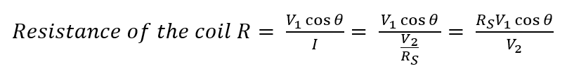
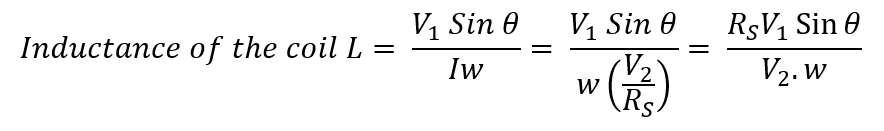
Voltage drop due to inductance of coil, IwL = V1 Sin Θ
Calibration of Ammeter
In the method of calibration of AC Potentiometer, the AC Ammeter is connected in series with a non-inductive variable resistance. The non-inductive standard resistor and a voltage drop across standard resistor are measured by AC potentiometer.
Calibration of Voltmeter
This method of calibration of AC voltmeter is similar to the calibration of DC voltmeter by using AC potentiometer.
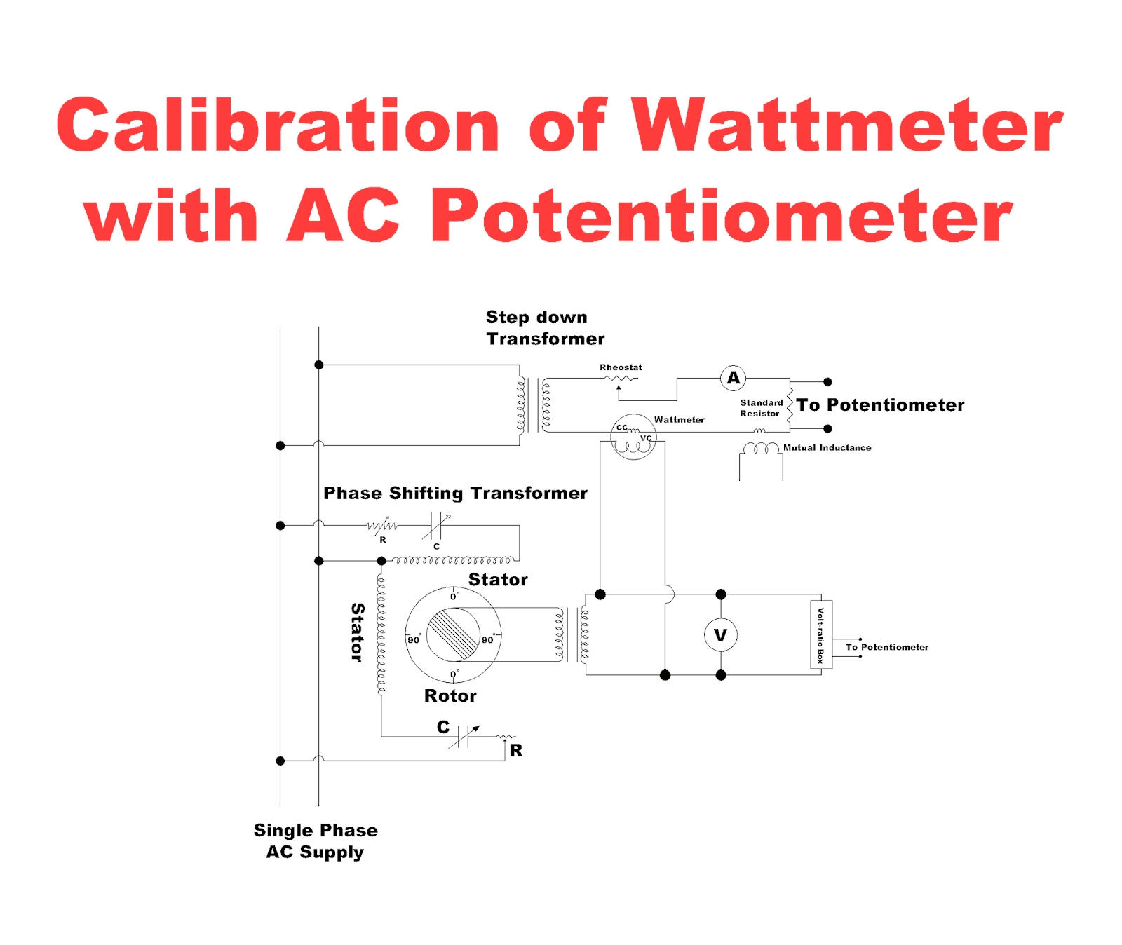
Calibration of Wattmeter
This procedure is same as the calibration of wattmeter by DC Potentiometer. The current coil of the wattmeter is supplied through the stepdown transformer and the voltage coil is supplied from the secondary winding of a variable transformer whose primary winding is supplied by the rotor of a phase shifting transformer.
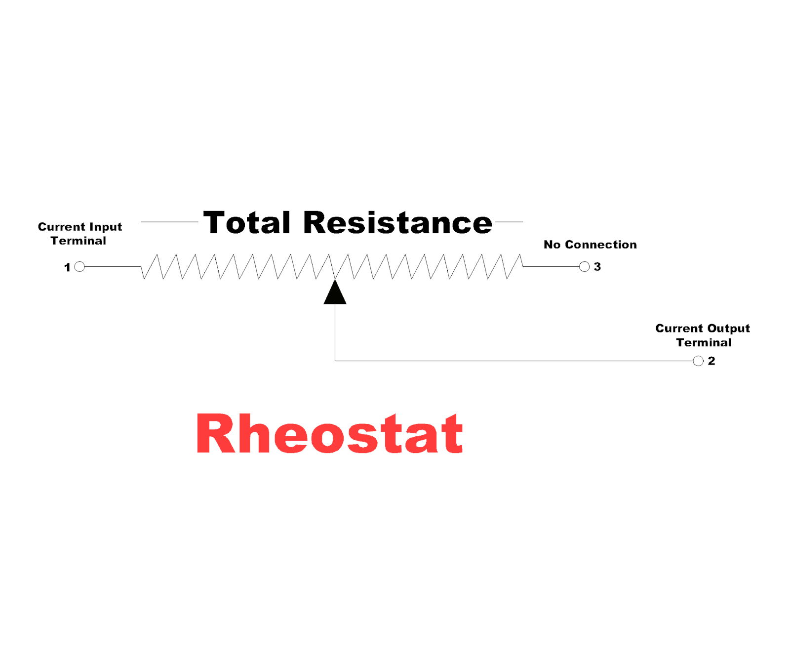
Difference Between Rheostat and Potentiometer
Rheostat are the variable resistors while the potentiometers act like voltage divider. The potentiometer provides variable voltage on its output while the rheostat is different from potentiometer and provides variable resistance on its output. A rheostat consists of 2 terminals while the potentiometers consist of three terminals and a sliding wiper. In rheostat, one terminal is connected to supply while the other contact is open and is used for output variable resistance with rotation but in potentiometer, two terminals of resistive element are connected to the supply and one terminal provides output variable voltages by rotating it.
Resolution of Wire-wound Potentiometers
Potentiometers are of two types according to its resistive element. These are wire-wound type and non-wire wound type. The resolution effects occur in wire wound potentiometers only and non-wire wound potentiometers are free from these effects. The resolution is used to measure the changings in output value of the potentiometer. So, lets discuss the resolution effects of wire wound potentiometers.
Resolutions are of three types and these all three types are discussed below:
Theoretical Resolution
This resolution is for the linear wire-wound potentiometers and it is also named as nominal resolution. The linear wire-wound potentiometers consist of a movable contact which is used to set for any turn of the resistance wire. Assume that N is the number of active turns in the resistive element, then the theoretical resolution in percent is given by:

The active turns of the resistive element represent the total resistance. Higher active turns of resistance in potentiometers have better theoretical resolution. The better theoretical resolution is the low theoretical resolution. Higher resistance values potentiometers have lower theoretical resolution.
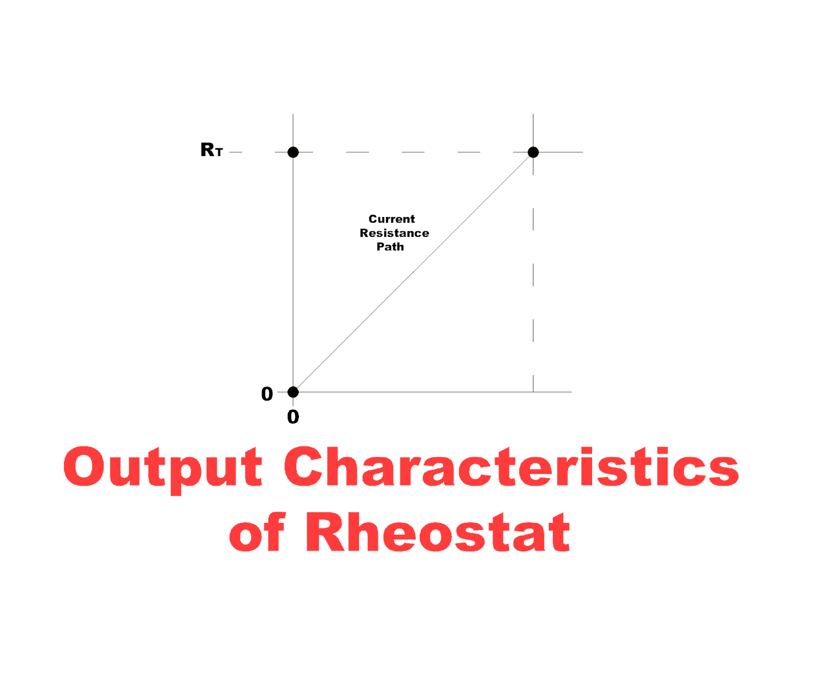
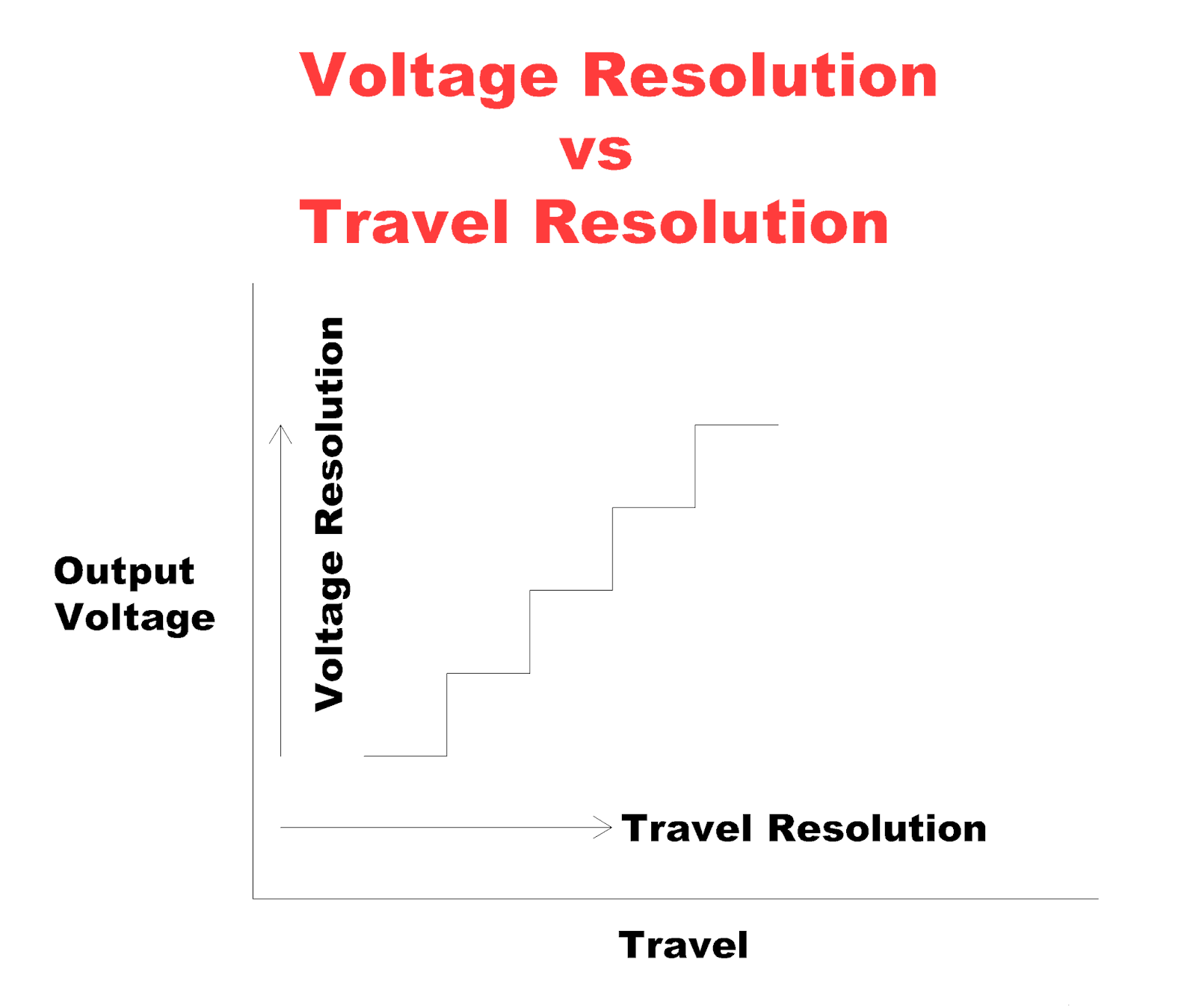
Travel Resolution
Travel resolution is the maximum movement of the mechanical input in one direction. It is required to add incremental step in the output voltage. It is specified in degrees in case of rotating input and it is specified in inches in case of linear actuating shaft. The output of these wire-wound potentiometers are in a staircase pattern as shown in figure. Theoretical resolution and travel resolution are the output response of the wire-wound potentiometers.
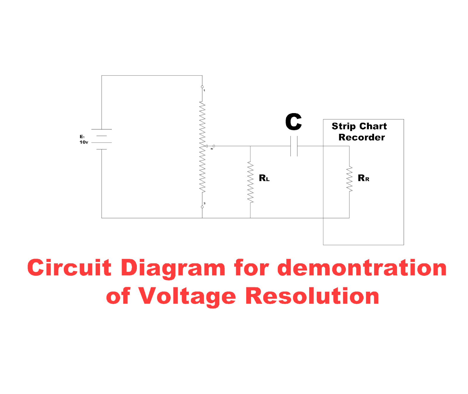
Voltage Resolution
It is defined as the huge incremental change in output voltage in any portion of resistive element with the movement of actuator/ shaft of the potentiometer. This resolution is applied to wire-wound potentiometers only. A circuit is shown in figure. As shown in figure the voltage source of 10v is applied to the potentiometer as input voltage.
Conformity of Potentiometer
Conformity is defined as the application of potentiometer that requires output voltage of a nonlinear potentiometer with respect to input voltage. Its formula is
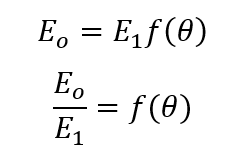
Eo is the output voltage, E1 is the input voltage and f (Θ) is the theoretical output function of the potentiometer. This function is specified with deviation from the theoretical function. This deviation of the output curve is conformity.

The figure below demonstrates the factors which affect the conformity of potentiometer.

Mechanical Travel
Mechanical travel is the amount of angular input rotation Θm which is necessary to move the wiper from one end to the other end. The output ratio of various wiper positions along mechanical travel is measured as shown in figure (B) above.
Electrical Travel
This is the amount of angular input rotation ΘA on which the output ratio actually varies. This range is observed by measuring the high and low end of points on the curve as shown in the above figure (C).
Theoretical Electrical Travel
It is the amount of angular input rotation ΘT. It is defined as the operational range of the potentiometer. This travel range is between the high and low theoretical end points as shown in figure (D). Mathematically its formula is given below:
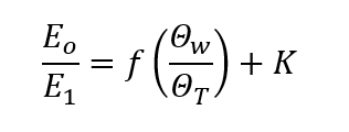
Where K is the conformity, Θw is the wiper position and ΘT is the theoretical electrical travel.
Absolute Conformity
Absolute conformity is defined as the total applied input voltage and voltage measured over theoretical electrical travel. It is maximum vertical deviation of the actual response from the theoretical curve. The following figure shows the absolute conformity.
Applications of Potentiometers
Potentiometers are used in various field and for various purposes. Potentioimeters have different function which are used in a vast range of electric circuits for the purpose of controlling, operating, measuring any value etc. Some of the applications of the potentiometers are given below:
Power Supplies
Potentiometers are used in power supplies for the adjustment of output voltages for various devices or circuits connected to the power supplies. Potentiometers are mostly used in variable Supplies for the adjustment of output voltage of supplies according to the load requirements. Potentiometers are also used for limiting the current in power supplies.
Operational Amplifiers
Potentiometers are used for the adjustments of voltage to set the gain of the operational amplifiers. These amplifiers are used for the adjustment of frequency of various channels, radios and for the audio control systems. These amplifiers are also used to increase the capacitance of various circuits with the help of potentiometers.
Digital Circuits
Trimmer potentiometers are used in all the digital circuits to adjust the time delay, clock frequency, thresh hold levels etc. These potentiometers are also used in integrated circuits for the use in digital circuits. 555 IC timer is the example of the time delay due to trimmer potentiometers.
Electronic Instruments
Trimmer potentiometers play a vital role in the electronic circuits for their use. Trimmer potentiometers are used in communication, computer, medical, manufacturing and in automotive instruments. Trimmer potentiometers are used in digital voltmeters to control the power supply, zero adjustment, amplifier gain control. Signal generators require oscillators, timing circuits, triggering circuits and trimmer potentiometers provide all these characteristics in signal generators. Trimmer potentiometers are also used in oscilloscope to control the power supplies, amplifiers, timing circuits etc.
