The secrets of DC machines with our in-depth guide on the “Construction & Working of DC Machines.” Explore the intricate details of the components that make up these electrical marvels, understand the fundamental principles governing their operation, and gain insights into the fascinating world of direct current machinery. Whether you’re a student, an enthusiast, or a professional in the electrical engineering field, this comprehensive exploration will enhance your understanding of DC machines, from their constructional features to their functional mechanisms.
A DC Machine can be used as a DC Motor as well as a DC Generator. Construction wise both are same but they have different working.
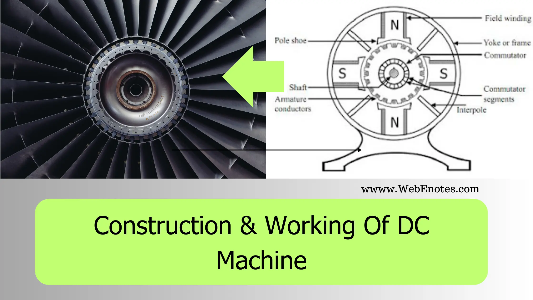
Construction Of DC Machine
The figure given below shows the Construction of a 4-pole DC machine.

4-POLE DC MACHINE
Essential Parts of the DC Machine are discussed below:
Yoke
Also called a Frame. The main function of the Yoke is to protect the internal parts of the machine from any mechanical injury, dust, or moisture. It provides mechanical support to the machine. It also provides the passage for magnetic flux produced by the poles.
For small machines, yoke is made up of Cast Iron and for large machines, it is made up of fabricated steel.
Pole And Pole Shoe
The Pole of a DC machine is like an Electromagnet. The field winding is placed on it and produces the magnetic flux. Poles are made up of thin cast iron lamination riveted together. The purpose of the pole shoe is to enlarge the cross-section area so that the reluctance of the magnetic path is reduced. It spreads the magnetic flux in the air gap more uniformly.
Field Winding
The purpose of the field winding is to produce the magnetic flux when an electric current is passed through it. It is placed on a pole and a small DC source is connected to it. The material used for Field Winding is Enamelled Copper Wire.
Armature
Armature is the rotating part of the machine and is cylindrical. It is made up of thin silicon steel lamination, which is circular and is riveted together. Thin lamination is used to reduce Eddy Current Loss.
On the outer periphery/circumference of the armature, slots are provided to accommodate the Armature winding.
Armature winding
They are placed in the slots provided on Armature. Made up of enameled copper wire and has multi-turns. When the Armature rotates, it will also rotate and an emf is induced in these winding.
Commutator
It is mounted on the same shaft as the Armature. Its function is to connect the rotating Armature winding to the stationary external circuit using brushes. It also provides uni-directional torque in the case of a DC motor.
The commutator is cylindrical and is made up of hard-drawn copper segments. These segments are insulated from each other by a thin sheet of mica.
Brushes
Brushes are placed and pressed upon the commutator and make a connecting link between the armature winding and the external circuit. Brushes are made up of high-grade carbon and it is placed in a particular position around the commutator by the brush holder.
Working on a DC Machine
As we said earlier, in Construction both DC motors and DC generators are the same but the working principles of both are very different.
Working On DC Motor
DC Motor converts the Electrical energy (in DC) into Mechanical Energy. The working of DC Motor is based upon the fact that, when a current-carrying conductor is placed in a magnetic field, then it experiences a mechanical force whose direction is given by “Fleming’s Left Hand Rule” and the magnitude of that force is given by:
F = B * I *L
where, F = Force Experienced by the conductor.
B = Flux Density
I = Magnitude of Current carried by conductor
L = Length of Conductor
Working Of DC Generator
DC Generator converts the Mechanical Energy into Electrical Energy (in DC). Its working principle is Faraday’s Law of Electromagnetic Induction which states that, whenever a conductor is placed in a varying magnetic field (or conductor is moved in a magnetic field), then an emf is induced in it. If the circuit of the conductor is closed, the current also starts flowing through it. The direction of the Induced Current can be determined by Fleming’s Right Hand Rule.
The magnitude of the EMF induced is given in the EMF Equation of the DC Machine.
