Star delta starter is one of the common motor starting techniques widely used in industry where there is a requirement of reducing the starting current. Let’s see the principles, advantages & disadvantages of Star Delta starter.
Although the Star Delta starter is not very popular but still today it is used in industries to reduce motor starting current and to efficient starting
The basic principle of Star Delta Starter:
Before going to the power and control circuit of the star delta starter let us see the basic principle. The basic principle of the star delta starter is that during starting the motor shall have star-connected winding and after some time when the motor has gained adequate speed the winding shall be converted to Delta winding. The advantage of this is that when the motor winding is star connected then the voltage in each phase is (the line voltage /1.732)
Suppose a 415-volt motor is to be started by a star delta starter. In that case, when the motor is starting that is the winding is in Star connection voltage across each phase will be 415/1.732. Due to this reduced applied voltage the starting current will also be reduced to 33.33%(1/3) of direct starting in the delta connection.
After the motor has attained a certain amount of speed (around 90% of the rated speed) and some voltage has been induced to its winding the winding will be switched to Delta. The motor will run in a delta connection.
The motors that are to be started by the Star Delta starter should have six terminals available, in the other form of starters the Motor has three numbers of terminals but for the Star Delta starter, 6 number of terminals are required because the winding has to be connected in Star mode once and Delta mode for the rest. Both the connections i.e. star and delta, are available inside the star delta starter, only the changeover is done during its operation. That’s why 6 nos. Of terminals are required.
Let us see the power circuit diagram of a star delta starter.
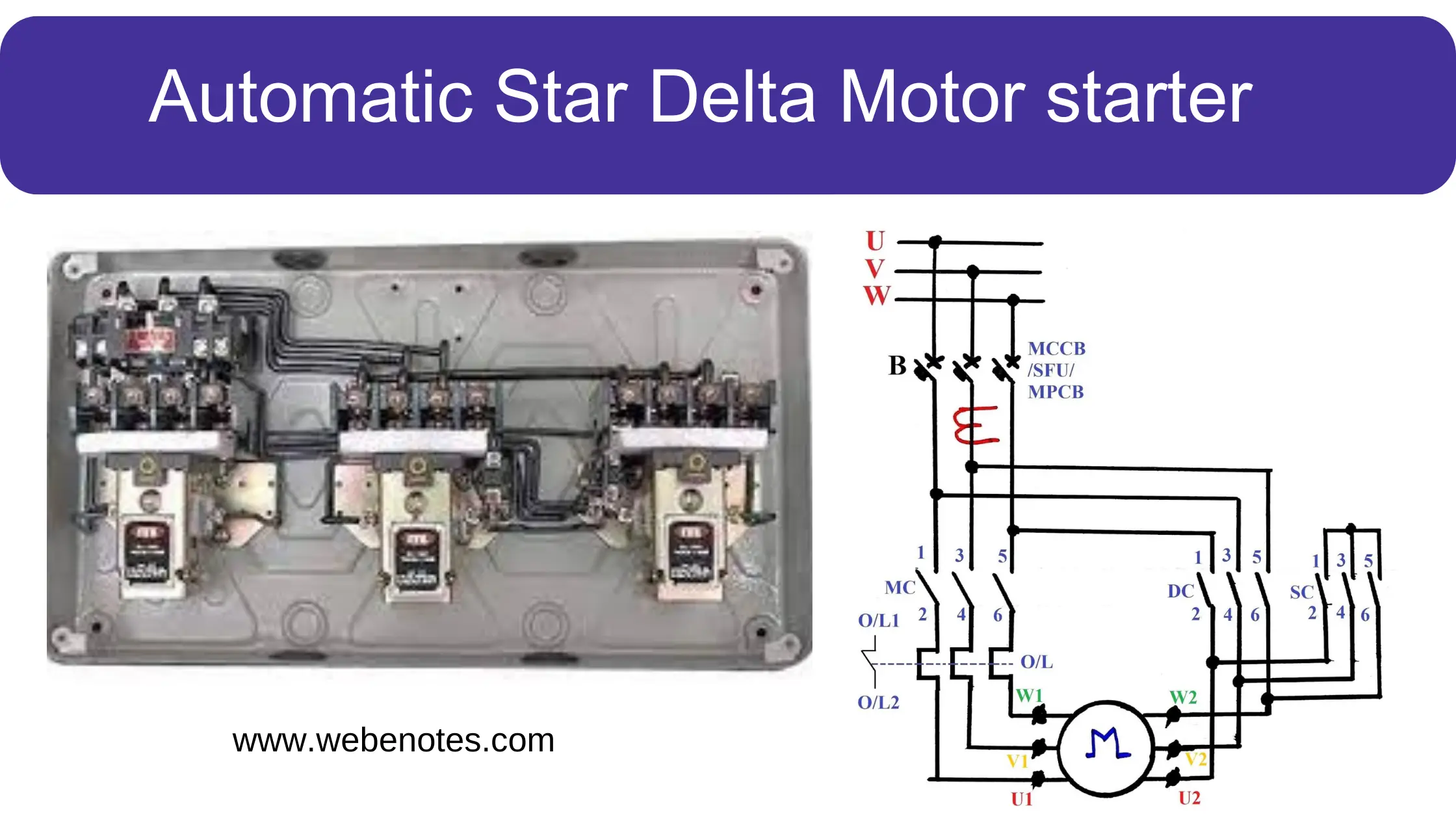
The power circuit of a Star Delta Starter is drawn below.
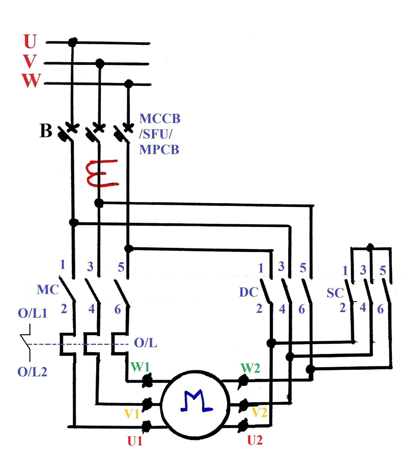
Fig 1: Automatic Star Delta Starter-Power Circuit Diagram
B stands for circuit breakers, which are MCCB, SFU, or MPCB. MCCB means Moulded Case Circuit Breaker, SFU stands for Switch Fuse Unit, and MPCB for Motor Protection Circuit Breaker. MPCB is a used motor rated up to 30 kW.
CT is shown which shall be used for current measurement or protection. CT shown In this drawing is for one phase only however 3 number of line CT with ammeter selector switch can also be used for current measurement.
The next component is the Contactor. There are three contactors shown in this drawing.
1. MC or main contractor.
2. DC or Delta contactor.
3. SC or Star Contactor
Now question may come as to why we need this contactor when we have the circuit breaker. Basically in this configuration, the circuit breakers are MCCB, SFU, or MPCB. They can trip the circuit automatically during any short circuit. Also, MCCB and MPCB can be tripped from the remote end (away from the switchboard) by using a shunt trip coil to the breakers but they can not be switched on by an electrical signal. These can be switched on by moving the grip only. So for remote operation, interlock with the processing system automatic switching on and off is required, which is achieved by the contractor. However, this explanation applies to the main contractor only. Star contactor and delta contactor are required to make the star and delta winding.
A bimetallic thermal overload relay is given for overload protection.
Rating of this switchgear component viz. MCCB/SFU/MPCB, contactor, and thermal overload relays for a particular motor are selected as per the Type 2 coordination chart, which can be easily found on the internet.
In general, a motor, up to 90 kW is fed by this arrangement however motor rated 110 kW and above has an air circuit breaker with a motor protection relay. The motor protection relay covers all the protection required, and the air circuit breaker can be controlled by an Electrical signal, so contactor or bimetallic relays are not used. But for forming the star and delta winding contactors will be required.
We have seen the power circuit diagram, now we shall focus on the control circuit. The control circuit diagram of the star delta starter is shown below.

Fig 2: Star Delta Starter-Control wiring diagram
Before starting the description please note that NO & NC stand for normally open and normally closed contact respectively. These states are applicable when the corresponding coil is at a de-energized state, suppose we say NO contact with a relay coil A, which means when A is de-energized then the contact is open, but when coil A is energized it shall be closed, an NC contact will open when the coil is energized.
Now let us see the components.
MC/DC/SC- Main/Delta/Star contactor coil. Energizing will convert NC contacts to open and NO contacts to close and vice versa when de-energized. Energizing it the main contact shall be closed to run the motor and de-energizing it shall cause the motor to stop.
Emergency Stop P.B.– The emergency stop push button switch, shall be installed near the motor. It is a stay-put type button that means when pressed it shall be locked at the new position. The push button is not shown in this drawing, however, it shall be connected in such a manner that pressing this switch will stop the motor irrespective of the motor operating locally or remotely.
Start P.B.– Push the button switch for the motor to start. It is a spring return type switch, which means after pressing it shall return to its previous position. It is a NO-type switch.
Stop P.B.– Push the button switch for motor stop. It is also a spring return type. It is NC type switch.
Both start and stop push buttons are located near the motor in a panel called “Local Push Button Station”.
So for starting the motor first have to close the circuit breaker or MCCB etc.
O/L relay contacts shall be normally closed. That means if the relay has not picked up it will be closed, when an overload occurs the relay contact will open and the control supply will be disconnected.
T- T is the timer. After the set time has over it switches over the motor connection from Star to Delta.
Now let us see the step-by-step principle to understand how the motor starts with start delta starter.
Step-1
To start the motor first the start push button to be pressed. Pressing this start push button will cause current flow through the timer coil and since the T1-T2 and DC7-DC8 are NC contact the SC will be also energized.
Hence the timer will start counting time, and all the NO contact of SC will be covered to closed contact, and NC will be converted to opened contact.
Hence SC 1-2, 3-4, 5-6, and 9-10 will be closed. And SC 7-8 will be opened. If you see the diagrams, you will see that this will cause
1. The start contact of the motor winding to close. So now the motor is in star winding.
2. Since SC 7, and 8 will be opened so delta contactor coil, DC will not be energised. So under no circumstances, there be any provision for a short circuit.
3. Since SC 9, and 10 will be closed, now the main contactor coil MC will be energised.
Step-2
Energization of the main contactor will result in the closure of contacts MC 1-2, 3-4, 5-6. Also MC 9-10 & MC 7-8.
So now even if the Start P.B is back to its NO state ( Since it is a Spring return type P.B) the main contactor coil will remain energised through MC 9-10, MC 7-8. Also, the SC coil is energized. So the motor will start at the winding connected in Star configuration.
Step-3
Now when the timer T will complete its set time its contact will change their state, i.e. T1-T2 will become Opened and T3-T4 will become closed. Although T3-T4 is closed it will not result in the Delta coil charging unless the SC is de-energised. Let’s see how.
1. T1-T2 has opened. So it will immediately de-energize SC. This will result in the opening of SC 1-2, 3-4, 5-6, 9-10; and the closure of SC 7-8. So main contactor coil will remain energised through its contact i.e. MC 7-8
2. Along with opening of T1-T2, T3-T4 will be closed at the same time. Now after the de-energization of SC, and closure of T3-T4, the DC coil will be energized, and its subsequent NO contacts will be closed, i.e. DC 1-2, 3-4, 5-6, and DC 7-8 will be opened, so there shall not be any provision of energization of SC.
So now the motor will run at Delta configuration.
In case the motor gets overloaded the overload relay will be energized and will make the O/L 1-2 contact open. So it will isolate the control supply, and the motor will stop.
Protection against short circuits and earth faults is given by MCCB, SFU, OR MPCB.
Advantages:
1. Economic starter.
2. Simple circuit.
3. Draws 1/3 times current than that required for starting the motor in direct online delta.
4. Not large, could be easily accommodated in switchboard panel.
Disadvantages:
1. Starting torque is also reduced to 1/3 of the starting torque developed in direct delta starting.
2. Very steep change in torque speed characteristics.
3. Needs 6 nos. of terminals, hence the motor needs to be specific.
4. Mainly used in low voltage systems.
5. Two (2) runs of cables are required.
6. The inclusion of so many numbers of contacts makes it unreliable.
Due to these disadvantages, star delta starter is not often used, and it is not a very recommended practice. The modern-day invention of the soft starter has replaced this almost.
