Phasor Diagram
Consider a transformer supplying the load as shown in Fig. 1.

The various transformer parameters are,
R1 = Primary winding resistance
X1 = Primary leakage reactance
R2 = Secondary winding resistance
X2 = Secondary leakage reactance
ZL = Load impedance
I1= Primary current
I2 = Secondary current = IL = Load current
now Ī1 = Īo + Ī2‘
where Io = No load current
I2‘= Load component of current decided by the load
= K I2 where K is the transformer component
The primary voltage V1 has now three components,1. -E1, the induced e.m.f. which opposes V1
2. I1 R1, the drop across the resistance, in phase with I1
3. I1 X1, the drop across the reactance, leading I1 by 90o

The secondary induced e.m.f. has also three components,
1. V2, the terminal voltage across the load
2. I2 R2, the drop across the resistance, in phase with I2
3. I2 X2, the drop across the reactance, leading I2 by 90o

The phasor diagram for the transformer on load depends on the nature of the load power factor. Let us consider the various cases of the load power factor.
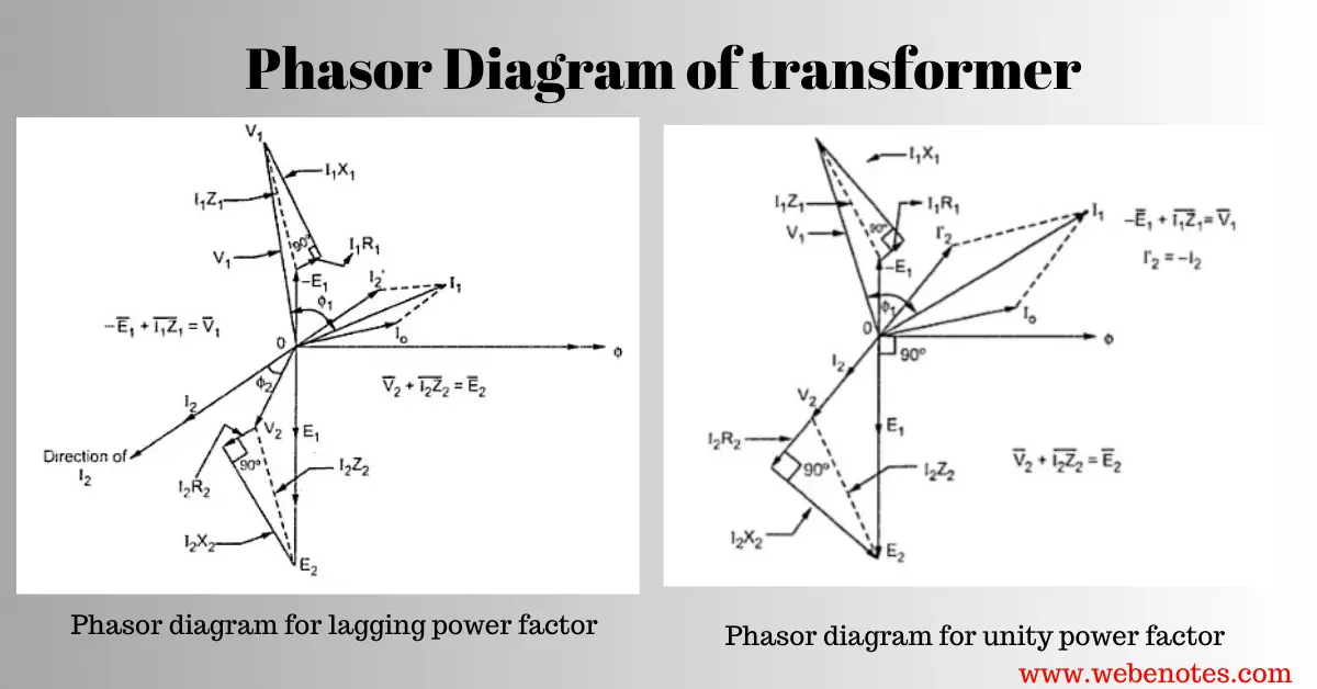
1.1 Unity power factor load, cosΦ2 = 1 As load power factor is unity, the voltage V2 and I2 are in phase. The steps to draw the phasor diagram are,
1. Consider flux Φ as a reference
2. E1 lags Φ by 90o. Reverse E1 to get -E1.
3. E1 and E2 are inphase
4. Assume V2 is in a particular direction
5. I2 is in phase with V2.
6. Add I2 R2 and I2 X2 to to get E2.
7. Reverse I2 to get I2‘.
8. Add Io and I2‘ to get I1.
9. Add I1 R1 and to -E1 to get V1.
The angle between V1 and I1 is Φ1 and cosΦ1 is the primary power factor. Remember that I1X1 leads I1 direction by 90o and I2 X2 leads I2 by 90o as current through inductance lags voltage across inductance by 90o. The phasor diagram is shown in Fig.2

Fig. 2 Phasor diagram for unity power factor load
Lagging Power Factor Load, cos Φ2:
As the load power factor is lagging cosΦ2, the current I2 lags V2 by angle Φ2. So the only change in drawing the phasor diagram is to draw I2 lagging V2 by Φ2 in step 5 discussed earlier. Accordingly direction of I2 R2, I2 X2, I2′, I1, I1 R1 and I1X1 will change. Remember that whatever may be the power factor of load, I2X2 leads I2 by 90o and I1X1 leads I1 by 90o. The complete phasor diagram is shown in Fig. 3.

Loading Power Factor Load, cos Φ2:
As the load power factor is leading, the current I2 leads V2 by angle Φ2. So change is to draw I2 leading I2 by angle Φ2. All other steps remain the same as before. The complete phasor diagram is shown in Fig. 4